The idea to create this crane, came up in the end of one of my earlier models. One day I was talking to one of my supervisers at
Technical University of Denmark, DTU, who works with control problems. We were speaking about LEGO, since we use a lot of LEGO in
the university at the Automation section. He told me that he always had wished to have a 'real' containercrane to control.
In a few minuttes I agreed to try to construct a large model in LEGO. The plan was to built a prototype of my own bricks,
equip this model with motors, sensors, and the necessary amount of RCXs, to control the whole crane.
If the model came up to be working well, DTU would try to get a sponsor to get the necessary bricks for a permanent model
which could be used for educational purpose in control exercises for other students.
) I contacted KONECRANES in Finland, which produces a lot of Ship-to-Shore containercranes (STS), and they were very helpfull
with pictures, drawings and technical data of the cranes, there by it would be possible to create a model as close
as possible to the real ones.
I contacted KONECRANES in Finland, which produces a lot of Ship-to-Shore containercranes (STS), and they were very helpfull
with pictures, drawings and technical data of the cranes, there by it would be possible to create a model as close
as possible to the real ones.
After some writings with KONECRANES, we find out that the model should be a crane which was recently setup on the
harbour of Barcelona, see the images to the right.
A Ship-to-Shore (STS) containercrane is a crane which can load and unload containers from a ship. They are often mount on two long ralls on the quayside, and it is thereby possible to drive along the quay and reach all the containers on the large ships. The containers are moved from the ship to the quay, where trucks moves them around and directly to the customers.
I choosed to built the the crane in scale 1:40, from an estimate of my amount of brick I could use for the project, and to bee able to setup the crane in a normal building with more than 2 meters to the ceiling. The scale 1:40, means that a normal container will be 1 foot long.
The data of the original crane can bee seen below.
 |
|
From the beginning of the project, it was the meaning that the first model should bee a prototype, therefore I did not use that much time of the appearence of the model, mostly weights, dimentions and speed, to make the crane behave like the real one as much as possible.
)
In the bottom of the containercrane you will find the Gantry Boggies, those boggies makes the crane capable of driving along the quayside on two heavy duty ralls. See the picture to the right.
The crane is equipped with too large "feet" with two boggies on each feet, every boggy contains 16 wheels, which carry the whole cranes (several hundred tons).
The LEGO model is also equipped with 4 boggies, a total of 64 wheels. In every boggie there is a 9V geared
motor, equipped with a second gearratio, which makes the crane drive on the ralls in the right speed, compared
to the scale.
The boggies run on two normal rails, equipped with toothbars to be able to control the position with a sensor.
) |
) |
I have made a small video, where you can see the crane moving sideways on the ralls.
Put a notice to the sound, the whole construction weight around 25 kg!
Sideways movement, Low resolution, 501KB
Sideways movement, High resolution, 2023KB
The videos can be viewed with Quicktime, get it here.
The crane is built on a heavy duty frame, to bee able to carry the weight of the moving containers. On top of the 4 boggies, is put two large rectangular frames, which in the bottom rests on the boggies, and in the top carries the boom. Between the two large frames there is a support boom in around 17 meters height. One the top there is two horisontal support-rods, and two diagonal rods to give the necessary stiffnes.
The two large frames, are made rectangular profiles in LEGO, with plates on two of the sides, and bricks on the
other sides, to give the necessary stability the plates are placed on the vertical sides.
So are the large horisontal frame in the bottom, but reinforced with Technic-beams to get the necesary strength.
To be able to transport the crane I have made alle frame parts with technic holes and axles in the end, to be
able to disassebly the crane quickly.
The frames in the top are made like "round" profiles, less heavy than the other frames since they only have to
take care of push and pull forces.
Size |
|
On top of the crane, there is a set for beams, to support the whole boom, both the main boom and flyjib.
It consist of to frames, mount on top of the two large rectangular frames. The front most, is a bit higher than
the rear one. Between those two frames, two small beams are mount to connect and stabilise the two frames.
Alle the beams on the crane are made as round profiles, but due to lack of bricks, some of the beams are
not all finished, only the part for the appropriate strength are made.
Sizes |
|
The containers are liftet and moved along a large boom, aligned across the quayside, i.e. from the ship and on to the quay, or opposite. The boom consists of two parts, the main boom, and the flyjib
The main boom, goes from the quayside, all the way through the frame, and around 40 meters behind the rear 'leg'.
The boom is mount under the top of the two rectangular legs. Four supportbeams, are mount between the main boom,
and the rear topframe.
The main boom and the topframe, support each other, and gives the necessary support for the flyjib.
Sizes |
|
In the front end of the main boom, the flyjib is mount, and reach around 51 meters out from the quayside.
In that way the crane it is possible for the crane to reach both sides of a large containership.
The flyjib is mount in two large hinges to the main boom, thereby it is possible to raise the flyjib up in the
air, to give more room for the ships to manouvre to the quayside.
In the outer end, and in the middle of the flyjib, 4 strong beams is attached between the flyjib, and the top
of the front topframe. Those beams, carry the whole weight of the flyjib, and load, when the flyjib is in its
working position.
In the outer end, is also attached a block of wires, which also goes to the top of the front topframe. With this block, it is possible to raise the flyjib to almost vertical position. It normally takes around 5 minutes to raise the boom. The motors for raising the flyjib are placed in a little house on the rear part of the main boom.
Sizes |
|
The trolley, contains the hoist mechanism for the container, inside the trolley, there are two large drums,
with motors, to lift the container up and down very fast, around 75 meters pr. minut with 60 tons of load!
The trolley is also equipped with motors for driving forward and backward along the boom. This speed is around
210 meters pr. minut.
In this model the hoist is driven by two normal 9V motors.
The containers hoist is made of 4 wires, and the hardest part of the design, is to make the 4 wires, lift
the container in the same speed.
If the 4 wires did not lift in the same speed, the container would not keep a vertical position in the hoist,
and therefore impossible to align with a truck or the ship.
On the real cranes, the diameter of the drum and wires, and the length of the wires, are very accurate
matched, to place the wire in one layer on the drum. If one of the wires is in two or more layers on the drum
the container will not be vertical when lifted.
The drums are made of 4 rims from 24x43 wheels, and I have made a systems of 4 wormscrews to place the wires
correct on the drums.
) |
) |
)
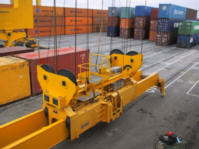
The spreader is that part of the crane, which grab the container. It is attached to the trolley by four wires, and
is thereby moveable up and down, along the quay, and along the boom.
The spreader is normally made with 4, a little longer than wide, pins. Since the pins are long, the container can be
grabbed by putting the long pins into 4 fitting holes in the container, turned 90 degrees and then the container is locked.
I have made the same system on this crane, to make it as real as possible. The pins are turned by a single 9V geared
motor, a system of axles and gears, connect the 4 pins.
) |
) |
This small video shows how the spreader is hoist up and down.
Hoist movement, Low resolution, 428KB
Hoist movement, High resolution, 1488KB
This video shows how the spreader is lowered, grabs and lock a contianer, and hoist it again.
Grap and hoist a container, Low resolution, 1079KB
Grap and hoist a container, High resolution, 5003KB
The videos can be viewed with Quicktime, get it here.
The first controller, is a normal manual controller, 3 functions controlled from a Technic Control Center, and the last two functions controlled from two ordinary switches.>br> When the crane was finished and tested, I transported to the Technical Univercity of Denmark, where it was setup in a laboratory for further extends and tests. The crane is going to be controlled by RCXs, and it is therefore necessary to equip the crane with motors and sensors for controlling the movement of the crane.
) |
) |
) |
) |
Four pictures of the crane in its place in the laboratory, it has been equipped with the following motors and sensors.
The crane is equipped with a total of 10, motors:
  GantryBoggies:   4 items, gearet 9V motors.
  Raise of flyjib: 1 item,  gearet 9V motor.
  Trolleymovement: 2 items, 9V motors.
  Hoist spreaders: 2 items, 9V motors.
  ContainerLock:   1 item,  gearet 9V motor.
The crane is equipped with the following sensors:
 Boggies
  Anglesensor for position of front boggie.
  Anglesensor for position of rear boggie.
  Pushsensor for endstop, each end, both boggies, total 4 items.

 Flyjib
  Pushsensor for endstop, top and bottom, total 2 items.

 Trolley
  Pushsensor for endstop, both ends, total 2 items.
  Anglesensor for position of trolley.

 Hoist spreader
  Pushsensor for topstop.
  Anglesensor for position of spreader.
  Anglesensor for anglemeassurement of wire, two directions, total 2 items.

 Spreader
  Pushsensor for present container.
  Pushsensor for containerlock.
The crane is equipped with 4 RCX controllers, to control alle the above mentioned motors and sensors.
The 4 RCX controllers communicate with each other and my an IR connection to a JAVA program on my PC.
The crane is handled with a 3 axis Joystick coupled to the PC.
X and Y direction of the Joystick, control the XY position of the spreader.
Z-axis on the Joystick (Throttle) controls the vertical position of the spreader. Alle the buttons, and
combination of the buttons are used for other controls, initilisations etc.
) |
) |
) |
The two set of boggies, are driving along the ralls, along the quayside. When it mooves, it is very important that
the front and rear boggie follow each other. If they dont, they can destroy the whole construction.
The first part of this control is to initialise the boggies to make sure the are at same position.
THe initalisation-rutine fullfilles this in the follow sequence:
Both boggies are started, and drives in the direction of the left endstop, under this manouvre the position
are controlled for both boggies.
When one of the boggies hit the endstop, it stops, and the controller stops controlling the position, and the
other boggies, drives the last distance to the end-stop. Now both boggies are reset, the controller is started again
and the boggies are ready for moving.
The movement are controlled from the computer by the X-axis of the Joystick. The initialisation is activated via a button on the Joystick.
) |
) |
)
The raise of the flyjib are controlled by a single motor and two end-stops. Normally the flyjib is in a vertical position
supported by 4 beams from the top of the crane. It can be raised by a wires between the flyjib and the top of the fram.
On the top of the crane is mount a top-stop which are activitated when the flyjib is in the desired vertical position, and stops
the motor. The bottom-stop was a little more difficult to make. There are noe specific place on the crane, where you can deside
when the flyjib is in vertical position. It is first fullfilled when the 4 beams support the flyjib.
I implemented it in this model by placing the motor for the flyjib on a small hinge, when it raises the flyjib,
it tilts a bit and so when the flyjib is lowered it will fall back on the sensor when the flyjib is in position, see the picture.
The raise of the flyjib is controlled by two buttons on the Joystick.
)
The trolley are controlled on almost the same way as the two boggies in the bottom of the crane. By initalisation, the trolley is
moved to the front endstop, position is reset and now the crane knows where the trolley is.
The trolley is also equipped with a controller to prevent the Spreader and maybe a containger of penduling,
more about that later.
The movement is controlled by the Y-axis of the Joystick. The initialisation is activated via a button on the Joystick.
)
The Spreader can be hoist up and down by a powerfull winch placed in the Trolley. Below the trolley is placed a topstop
to prevent the Spreader for beeing hoist too close to the Trolley. This topstop is also used for initilisation.
Then the calculated position from an anglesensor in the winch, can be used as bottomstop.
The movement is controlled by the Z-axis of the Joystick (Throttle). The initialisation is activated via a button on the Joystick.
The ContainerLock is controlled by to pushsensors and a motor. The Motor can turn the 4 locks 90 degrees, to lock the container
to the Spreader. One of the sensors are mount to see it the 4 locks are in position Locked or Unlocked.
The other sensor is activated if the spreader are on top of a container, and the 4 locks fits in the 4 holes in
the container.
Picking up a container is like this:
First the spreader is lowered onto a container, and the 4 locks fits into the 4 holes
in the container. The first sensor gets activated "container present". The other sensor is "Unlocked", the motor for the locks
turns by this signal. When the four locks are locked, the other sensor is pressed to "Locked", and the container is now ready to
be hoist up. When the container is hoist there is a little slack in the locking mechanisme, which
make the sensor "container present" to be deactivated, "no container present". Now the container can be moved, and the
software prevents the container from beeing dropped by not allowing the locked to bee turned, when the two sensors
say "no container present" and "locked".
When the container are lowered onto a surface, the spreader fall down on the container again and the first sensor goes to
"container present", the other sensor is "locked", and motor turns the 4 locks to the position "unlocked" and the spreader
can now be hoist and moved around. The sensor-system almost prevent agains falty containerhandling.
The whole idea of the project is to try to control the movement of the spreader, that means, to prevent the spreader from penduling uncontrolled. Normally a good cranedriver can prevent the spreader from penduling, and if it should happen, the driver is able to stop the penduling by moving the spreader in the right directions. The idea is to control those movement, and help the driver to prevent the penduling, and if it should happen the controller will stop the penduling very fast and efficent. In this way it maybe will be possible some day to move the containers automaticly.
To be able to make a controller, 3 things has to bee present: A system to control, a sufficient sensor for the problem
and an actuator to control the system.
In this case it is the movement of the trolley we want to control, from the movement of the spreader.
The actuater are the motors in the trolley.
The sensor for determining the movement of the spreader is implementet via a anglesensor from the company DCP-Micro.
This sensor has a better resolution than the standard anglesensor from LEGO. The anglesensor is coupled to one of
the wires that goes from the trolley to the spreader, and is thereby capable of reading the angle of the spreader. This
angle is supposed to be vertical.
) |
) |
The first controller I have implementet is a proportional-controller, dayly called P-controller. It is the most simple controller to make, and it works like this. The angle is meassured, multiplied by a gain, and this is the signal to the motor. That means, if the spreader is hanging one way, the trolley follows in this direction, and opposite. If the angle is large, the trolley runs fast, and if the angle is small, the trolley runs slowly.
The result can be seen on this video, where the controller dampens the penduling pretty fast.
P-controller, High resolution, 1314KB
The videos can be viewed with Quicktime, get it here.
The other controller I have implementet is a lowpass-controller, which are fare more efficient than the P-controller , since it also meassures the speed of the spreader, not only the angle. That means if the spreader is moving back again, then the controller knows that it should not correct the angle but the movement. The term lowpass, is because the meassured angle of the wire is put throug a lowpassfilter, and added to the error of the position of the trolley. This type of controller are a lot faster than the P-controller
The result can be seen on this video, where the new controller makes the spreader stable.Since the description ends here, I better give a little conclusion to the project status right now.
As mentioned in the beginning, the plan was to exchange my model with a permanent model to be setup at DTU,
and used for different tests for other students. Regrettably DTU didn't succeded in getting a sponsor to the
large amount of LEGO used for the model for a permanent model. My model performed well, and it is clear that
it is very usefull, for experiments. But since I dont want to donate my bricks, the project is so far stopped here.
I really liked to work more on the projekt, but since there is no time in my study right now, I had to stop the
project. All data are saved, so if some bricks suddenly show up it would be possible to continue the project again.
Status of the project until now, is that the crane is capable of damping penduling movement of the spreader in
the longtitudinal direction of the boom. The controller is not perfect, but the P- and Lowpass-controller showed
that it is possible to control the spreader.
Future extensions would be to be able to control the crossdirectional penduling of the spreader. And
the controller could be improved, and later on, it could be nice to be able to move a container from one
position to another automaticly. Time will show.
Below I have listed the final data of the LEGO model.
|
|
For those of you, specially interrested in the project, I have a list of the bricks I have used for the crane. The bricks I have used are not the optimal ones, since I had to use the bricks I have, a final model could use less and bigger bricks. All the 'holes' in my construction could be filled in a final model, to get the best appearence. If You are would like a copy if the list of bricks, please send an email.

)
)
)
)
)
)
)
)
)
)
)
)
)
)
)
)
)