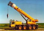
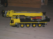
Grove GMK 4075 All Terrain Crane
Motivation
The motivation to built this cranes was rather spontaneous, a local haulage contractor, Henning Petersen A/S
added in march 2003 a 75 ton mobile crane, Grove GMK4075 to the company. I have had the chance to follow the crane on
a few jobs. The crane caught my interest and I thought it could be fun to create a model with LEGO bricks.
In November 2003, I started to build the crane, and it was finished about 14 days later.
The goal in this construction, was to built a functional model, it was not important to me that the occurence was
correct, but to built a 4-axle mobile crane with a telescopic arm, and a luffing flyjib.
Data
I choose to built the crane in the scale 1:20, compared to the time it will take to construct the crane, and
former experiences from other telescopic cranes. It is very often a problem to construct a long boom, because
of the dimension and weight of LEGO bricks. A lot of telescopic sections gives a very heavy boom, which the
LEGO hardly can handle.
Some of the data I used during construction of the crane, is listet here below, if you are interested you will finde more here.
 |

| Max capacity |
80 t |
|
| Boom length |
43.2 m |
|
| Telescopic sections |
4 |
|
| Jib length |
10- 27 m |
|
| Engine |
Mercedes-Benz 422 HP |
|
| Drive and Stearing |
8x8x8 / 8x6x8 |
|
| Top speed |
78.5 km/h |
|
| Gross Vehicle Weight |
48 t |
|
|
LEGO model
Below I have made a discription of the crane construction in details.
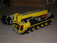
Chassis
The chassis on the original crane is made with 4 axles which can be individually controlled.
That gives mainly 3 different way of driving; Drive normally - rear axle locked, turn around the
center of the crane, and last, move sideways.
I have chosen to construct the chassis which can turn around the center, if every axle should
have been controlled individually, it would demand a lot of linking and gear ratios between the
axles, which is hard to put into this little model.
The stearing is controlled with one axle that goes from front to end. It is equipped with different
size of gear wheels, which gives different angle of the wheels. One size of gear for axle 1 and 4, and
a smaller gear for axle 2 and 3.
The stearing rod is placed in front of axle 1 and 2, and behind axle 3 and 4. This implementation gives
a precise stearing without that much backlash.
All axles on the model are individually suspended with the small LEGO parts 0732 and 0731.
The axles are mounted on a small rocker arm, and in the junction is placed a universal joint to manage the stearing. The long axle for
stearing is placed above every rocker arm. The stiffness of the suspension are adjusted to match the weight of the crane.
The balance is best when the crane is equipped with a tiny counterweight, because of the missing part of the superstructure and
crane cabin.
Turntable
The turntable of this crane is constructed around the big Technic turntable 2855 and 2856.
The large gear wheel on the rim of the turntable is connected to a small gear which are driven by a small crank handle
on the left side of the chassis.
After the first attemp of the construction it was clear that the turntable could not handle the big pressure, and
a difference between the load and the counterweight.
The solution of the problem was to construct a few rollers in the superstructure, to distribute the pressure on a larger
area of the chassis. There are one roll in the front, rear and both sides. The rollers are made of a little Technic wheel.
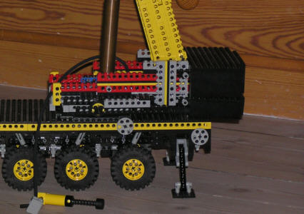
Superstructure
The part of the crane which has been rebuild most times are the superstructure. The main boom has been changed a
lot of times and that demands a reconstruction of the superstructure. The pictures shown on the site are unfortunately
only showing the last rebuild of the superstructure which miss some parts, only the junction for the main boom,
main cylinder, counterwieght and turntable are made. The cabin for the crane driver and the winch for the hoist are removed.
On the rear of the superstructure I have made a system for carring the counterweights. I have made two counterweights
for this crane. The first and smalles are made of 8 standard LEGO train weights 73090
which gives a total weight of about 0.5kg. The other one is built around a block of steel with a weight of
about 1 kg.
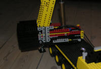
The junction for the main boom and main cylinder are very heavy made, to handle the big load. When the
crane is raised from horisontal equipped with the jib, the load on the superstructure is very high, and it is
easy to see the LEGO bricks bend alarmingly.
 |
 |
Main boom
The most difficult part to build on a mobile crane with a telescopic boom is the boom itself. Because of the size
of a LEGO brick, many telescopic sections gives a very big arm in the bottom and a very thin arm in the top.
The real crane is equipped with 4 telescopic sections, I have chosen only to create 3 sections, because of the problem mentioned
above. The inner section is 2 bricks wide and the outer is 8 bricks wide. A telescopic boom in LEGO gets very heavy with
more sections, and that gives a limit to the lengt.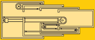 The boom is constructed with 2 Technic beams above each other, with two flat bricks in between, to give the boom sufficient strength.
By every junction between sections the boom is equipped with a huge reinforcement to handle the heavy torque.
The first version of the boom was constructed with a system of wires to extend the boom. The wires are coupled so you
only have to pull the first wire, all the other wires and sections are coupled together and that makes it possible to
extend all section at the same time, only by pulling the first wire. The disadvantage is that you have to pull
very hard in the first wire, when a the crane carries a big load. The system is shown in the figure to the right, but the
first wire is replaced by a hydraulic cylinder to extend the first section.
Because I wanted to equip the main boom with a Luffing Jib, I had to reinforce the main boom, and I did not construct
a new and heavyer system to extend the main boom on this second version.
The boom is constructed with 2 Technic beams above each other, with two flat bricks in between, to give the boom sufficient strength.
By every junction between sections the boom is equipped with a huge reinforcement to handle the heavy torque.
The first version of the boom was constructed with a system of wires to extend the boom. The wires are coupled so you
only have to pull the first wire, all the other wires and sections are coupled together and that makes it possible to
extend all section at the same time, only by pulling the first wire. The disadvantage is that you have to pull
very hard in the first wire, when a the crane carries a big load. The system is shown in the figure to the right, but the
first wire is replaced by a hydraulic cylinder to extend the first section.
Because I wanted to equip the main boom with a Luffing Jib, I had to reinforce the main boom, and I did not construct
a new and heavyer system to extend the main boom on this second version.
To raise the main boom, I use a pneumatic (air under pressure) cylinder. On the first version I used 8 of the normally
double-acting pneumatic cylinders. They were coupled in pars, 4 pairs in the end of each other. It was not a very pretty solution
and it did not have enough power to raise the main boom with flyjib. A couple of years ago I tried to make a truck with a tip trailer,
here I also ran into lack of power, and my father helped my to make another cylinder with larger diameter and longer working range.
The cylinder is 3 bricks wide and has a working range of 14 bricks.
With a diameter of 3 bricks, the force is 2.25 times bigger than a normal LEGO cylinder. Which is enough to raise the main
boom with flyjib on the crane.
Overall the main boom is 1.8 m fully extended, and 0.56 m all withdrawn. The boom can be raised to about 87 degress.
Flyjib
A mobile crane with a normally main boom, often has a problem about reaching something far away from the rim of for example a tall building.
If the crane for example has to reach something 15 meters from the rim of a 30 meter tall building, it has to be really high if it
is not equipped with a luffing flyjib.
The Grove GMK4057 is equipped with a jib which can be luffed. The arm is mountet on the end of the main boom before the
main boom is raised, it can be from 10 to 27 meters and it is luffed with a hydraulic cylinder.
I have also equipped my LEGO model with a luffing flyjib, because of the weight I had to reduce the length to 0.6 meters.
In the middle of the jib, there is a pneumatic cylinder to luff the outer part of the jib.
By transport a part of the jib is placed on the right side of the main boom, extra pieces to extend the jib to 27 meters
can be put on a small trailer.
The jib is equipped with a pivoting junction which fit on the end of the main boom.
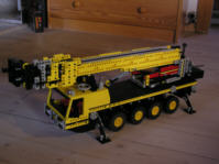
The result
It has been a challenge to built this model, regrettably it was hard to built in the correct scale compared to the
length of the main boom, since the strength and weight of LEGO arent optimal for telescopic booms.
But the crane reaches a maximum height of 2.4 meters and are fairly stable. The crane is not able to lift a heavy load since
the main cylinder only is able to lift the boom itself, this is rather normal for LEGO models, the biggest challenge is to
get the crane cabable of carring its own weight.
The model was not ever completely finished, other projects caught my interest, but mayby I will try to rebuilt the
crane again some day. And there will be another opportunity to take some better photoes of the crane outside.
Data
Below I have put the final data of the LEGO model.
 |
|
| Max capacity |
Not tested |
|
| Max height |
2.4 m |
|
| Main boom |
1.8 m |
|
| Telescopic sections |
3 |
|
| Flyjib |
0.2 - 0.6 m |
|
| Engine |
none |
|
| Drive and stearing |
8x0x8 |
|
| Gross vehicle wieght |
2.4 kg |
|
| Max counterweight |
1.5 kg |
|
|
Setting up the crane
Setting up this kind of mobile crane is done in 3 steps. Placing the crane, mounting the jib, raise and extend main boom.
Below I have made a little series of picture to show the set up of my model.
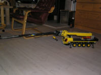
 |
The crane has arrived to the lifting place, the centerstearing makes it possible to get into small places. |
 |
The outriggers are placed to give enough support for the crane. |
 |
The jib is mountet in the front right end, svung around, and attached to the main boom. |
 |
The outer luffing part is raised from ground. |
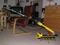 |
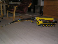
The fully withdrawn main boom with flyjib is raised. |
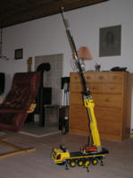 |
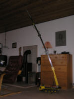
The main boom is raised to an almost vertically position. |
 |
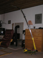
First telescopic section. |
 |
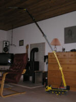
Second telescopic section. |
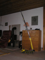
 |
When the ceiling is creating a limit, the outer part of the flyjib is lowered to a horisontal position. |
 |
The heavy counterweight is mountet to give the crane enough support, and the third and last telescopic section is extended. |
)
)
)
)
)
)
)
)
)
)
)
)
)
)
)
)
)
)
)
)
)
)